When harnessing the accuracy of an electronic compass, a number of factors, including magnetic conditions, can greatly impact performance. Here are two examples of these conditions and how to fix them.
1. Static Permanent Magnetism
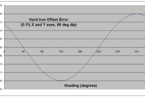
The source of a local permanent magnetic field can be a piece of hard iron (hence the common name), a constant DC current, or some other type of magnet. This source of error can be significantly reduced by calibration. The curve in Figure 1 shows that a residual error of 0.1% of the earth’s magnetic field on both X and Y axes produces a peak accuracy error of 0.2° at 66° inclination (dip angle in middle US latitudes).
The error varies sinusoidally with direction and produces a single cycle for each rotation of the electronic compass. Phase depends on the signs and magnitudes of errors on each axis. The magnitude of the error depends on magnetic inclination because the residual hard iron error is expressed as a fraction of the total field strength.
Fortunately, a residual Z-axis error is less critical. This error comes into play only when the electronic compass is tilted from level. At 30° tilt, a Z-axis error of 0.3% would be required to produce the same 0.2° peak accuracy error at 66° dip. The accuracy error decreases with decreasing tilt.
This is fortunate because it can be difficult to determine the Z-axis hard iron coefficient. When the electronic compass is mounted in a large vehicle it is impractical to turn the vehicle over in order to get sufficient calibration data. An estimate of the Z coefficient can be made as long as some tilted data is collected but a reasonable estimate may still require tilt angles that can’t be achieved.
To eliminate this problem, the electronic compass allows an optional two-step Z-axis calibration. Reference data is first collected outside the vehicle in an area free of magnetic interference. When the electronic compass is mounted in the vehicle, the measured vertical component is compared to the reference data to calculate the coefficient. As long as the electronic compass is within a few degrees of level during both measurements the calculated result is accurate.
2. Static Induced Magnetism
When you bring a magnet in contact with a metal paper clip the paper clip becomes magnetized. When the magnet and paper clip are separated, the paper clip no longer retains its temporary, or induced, magnetism. Soft iron, alloys of iron and nickel, common steel, and some types of stainless steel can all be easily magnetized, even in a weak field.
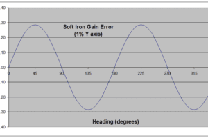
When these materials are in the vicinity of the electronic compass and rotate with the electronic compass, they become magnetized and demagnetized depending on their orientation to the earth’s magnetic field. Instead of seeing a constant field that would produce a perfect circle as the electronic compass turns, the electronic compass sees a field of varying magnitude that maps an elliptical shape. This induced magnetism gives rise to a heading accuracy error as shown in the example of Figure 2.
When the electronic compass is rotated in a level plane, the error varies sinusoidally and produces two cycles per revolution of the electronic compass. In figure 2, peaks are located at 45°, 135°, 225°, and 315° because the gain error is aligned with the Y-axis, which would be the major axis of the ellipse. For real-world applications, the major axis could be aligned at any angle.
In three dimensions, the locus of points would map to an ellipsoid instead of a perfect sphere. In this case, a 3×3 matrix of gain coefficients is needed to compensate. A minimum of 12 independent measurements is needed to determine 9 soft-iron gains and 3 hard-iron offsets.
If the electronic compass is only being used near level, then a simpler, two-dimensional compensation may be adequate. The electronic compass PC software includes an algorithm to estimate 2D soft-iron coefficients based on the approach set forth in “Direct Least Squares Fitting of Ellipses,” by Fitzgibbon et al. in IEEE Transactions on Pattern Analysis and Machine Intelligence, Vol. 21, No. 5, May 1999. The software reports the ellipticity, in percent, of the ellipse that best fits the collected data. This metric can be used to decide if soft-iron compensation is needed.
In situations where soft-iron is significant, it may be better to relocate the electronic compass. First, a two-dimensional compensation is only approximate, and small variations in tilt may produce dramatic changes in the soft-iron ellipse. Proper compensation may require that three-dimensional data be collected and analyzed to produce the full 3×3 gain matrix.
Second, soft magnetic materials that give rise to induced magnetism also exhibit varying degrees of remanence, the tendency to remain magnetized after a magnetizing force is removed. The magnetization of the material may change over time due to exposure to vibration, temperature changes, and varying electrical and magnetic fields. This results in hard-iron errors that must be periodically compensated to maintain accuracy.
If there is no alternative and 3D soft iron must be compensated, the electronic compass PC program provides an option to collect 3D data and calculate the optimum 12 compensation coefficients. The iterative algorithm works to find the ellipsoid that best fits the collected data by minimizing the sum of the squared geometric distances between the collected data and the parametric ellipsoid.


