Military, marine navigation, unmanned vehicles, and more depend on the accuracy of an electronic compass. There are several factors that can greatly influence how a compass takes its readings. Here are three of these factors and how to be aware of them.
#1 Time-Varying Magnetic Fields
A time-varying magnetic field in the vicinity of an electronic compass cannot be compensated. Its frequency must be above the pass band of the compass (i.e. greater than 30 Hz), or it must be eliminated. The compass measurement cycle rate of 27.5 Hz is chosen to maximize attenuation of 50 Hz to 60 Hz signals associated with AC power systems.
To estimate the order of magnitude effect of a DC current near the compass’ magnetometer, use Ampere’s law to calculate the magnetic field near a long wire:
A long wire carrying 25 mA of current located 50 mm from the magnetometer produces a 1 mG (100 nT) magnetic disturbance at the sensor. In the middle of the US, where inclination (dip angle) is roughly 66° and the earth’s magnetic field strength is about 500 mG, this can result in a 0.3° heading error.
#2 Tilt Measurement Errors
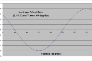
Errors in pitch and roll measurements give rise to single-cycle heading errors that cannot be differentiated from heading errors caused by residual hard-iron. The plot in Figure 1 shows how an error as small as 0.1° on both X and Y axes affects heading accuracy at 66° magnetic inclination (dip angle). The phase of this curve depends on the relative signs and magnitudes of the separate X-axis and Y-axis errors.
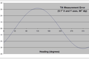
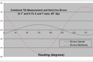
Compare the shape and phase of the curve in Figure 2 to the hard-iron error curve in Figure 1. In this case, the curves are not in phase, and the two sources of error tend to cancel each other. The resulting peak error is reduced by a factor of three as shown in the curve labeled “Errors Cancel” in Figure 3. But change the signs on both pitch and roll errors, and the two curves align in phase, producing the “Errors Reinforce” result also shown in Figure 3.
Tilt measurement errors can be caused by one or more of the following:
- Sensor offset and/or gain errors
- Sensor cross-axis coupling
- Misalignment of tilt and magnetic sensor axes
- Uncompensated horizontal acceleration
- Poor sensor quality
In applications where the electronic compass cannot be held perfectly steady, the error due to horizontal acceleration can be pronounced. Although the rate gyros (eCompass ECG and ECV) will initially compensate, if the acceleration persists, it will eventually affect the measurement. For a modest constant horizontal acceleration of 0.05g (roughly 1 mile per hour per second), the tilt measurement error is 2.9° (obtained by calculating tan-10.05). For the example 66° magnetic inclination used above, the result is a sinusoidal heading error of 6.5° peak magnitude.
#3 Magnetic Inclination (Dip Angle)
Near its magnetic poles, the overall strength of the earth’s magnetic field increases. But the horizontal component decreases substantially, making navigation by magnetic compass nearly impossible. For mechanical electronic compasses, the needle dips excessively, trying to align with almost vertical lines of force. For an electronic compass, accuracy decreases because the horizontal field is smaller and because the effect of tilt errors is more pronounced.
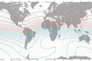
The map in Figure 4 shows lines of constant dip angle around the globe. Each of the lines is separated by 2°. The map is based on the US/UK world magnetic model for the year 2005.
Near the magnetic equator, tilt measurement errors have very little influence on electronic compass heading. Between ±5° dip, a 1° error in tilt produces no greater than 0.09° heading error. In northern Alaska (80° dip), the same 1° tilt error results in as much as 6° heading error.


